 Construction Line Add Command
Default Shortcut: c + a
Add a construction line by locating two points, a point and an angle, or base multiple construction lines off a parallel item in Modeling or Drawing Editor.
- Two Points
- Angle
- Parallel Item
- Base Off Line
- Tips and Tricks
- Related Tools
1 . Invoke Add Construction Line using one (1) of the following methods:
▸ Click the Add Construction Line icon, which is pictured above. The icon can be found on the Layout page > Layout section.
▸ Add Construction Line can also be invoked using the Find Tool by searching the command name and clicking the Add Construction Line icon, which is pictured above.
Learn more about alternative methods for launching commands.
2 . Locate- Pan -Return mouse bindings become active along with various Locate options.
3 . Select the Locate icon you want, then move your mouse pointer ( ![]() ) so that the point location target (
) so that the point location target ( ![]() ) snaps to where you want the first point of your construction line located, then left-click ( Locate ).
) snaps to where you want the first point of your construction line located, then left-click ( Locate ).
Note: Auto , INCL , INRL , EXPT , FRPT , VTPT , DXDY , MDPT , CNTR and ONLN can be used to locate points; TANC and POLAR can be used to add a second point.
4 . Locate- Pan -Return mouse bindings continue to be active. Select the Locate icon you want, then move your mouse pointer ( ![]() ) so that the point location target (
) so that the point location target ( ![]() ) snaps to where you want the second point of your construction line to pass through, then left-click ( Locate ).
) snaps to where you want the second point of your construction line to pass through, then left-click ( Locate ).
5 . A construction line is drawn through the two points. Right-click ( Return ) if you are done.
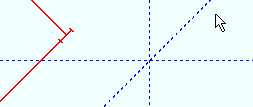
Note: Locating the same point in steps 2 and 3 (above) draws a construction line through that point at a 90 degree angle (vertical on the screen).
Another way that you can create construction lines in Modeling or the Drawing Editor is to locate a point through which you want the construction line to go and the angle you want the construction line to be at. The Locate option ANGL lets you designate any angle. The option PERP draws a construction line perpendicular to an existing construction line.
1 . Invoke Add Construction Line using one (1) of the following methods:
▸ Click the Add Construction Line icon, which is pictured above. The icon can be found on the Layout page > Layout section.
▸Add Construction Line can also be invoked using the Find Tool by searching the command name.
2 . Locate- Pan -Return mouse bindings become active along with various Locate options.
3 . Select the Locateicon you want, then move your mouse pointer ( ![]() ) so that the point location target (
) so that the point location target ( ![]() ) snaps to where you want the first point of your construction line located, then left-click ( Locate ).
) snaps to where you want the first point of your construction line located, then left-click ( Locate ).
Note:Auto , INCL , INRL , EXPT , FRPT , VTPT , MDPT , CNTR and ONLN can be used to locate points.
4 . Locate- Pan -Return mouse bindings continue to be active. Select the ANGL or PERP Locate icon.
Alternative 1 :If using AGNL, left-click ( Locate ) anywhere in the model or drawing area.
Alternative 2 : If using PERP, select the construction line you want your new construction line to be perpendicular to.
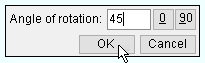
5 (for ANGL only) . Enter the angle that you want the construction line to be rotated from horizontal. Select OK.
6 . A construction line is drawn through the two points. Right-click ( Return ) if you are done.
Both Modeling and the Drawing Editor provide Locate options for generating up to 100 construction lines that are parallel to lines, construction lines, straight grid lines, or to member work lines . The Locate options you can use to do this are BSMB , BSCL and BSRL .
1 . Invoke Add Construction Line using one (1) of the following methods:
▸ Click the Add Construction Line icon, which is pictured above. The icon can be found on the Layout page > Layout section.
▸Add Construction Line can also be invoked using the Find Tool by searching the command name.
2 . Locate- Pan -Return mouse bindings become active along with various Locate options.
3 . Select the BSMB , BSCL or BSRL Locate icon you want.
Alternative 1 : If using BSMB, left-click ( Locate ) on the member or member line (if displayed in stick) you wish for your new construction line to be parallel to.
Alternative 2 : If using BSCL, left-click ( Locate ) on the existing construction line you wish for your new construction line to be parallel to.
Alternative 3 : If using BSRL, left-click ( Locate ) on a line or polygon side you wish for your new construction line to be parallel to. If you are using this snap in modeling, the line selected must be from a reference drawing that is shown.
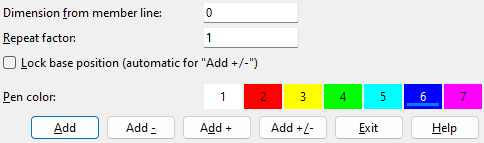
4 . Enter the dimension from the selected line above, the repeat factor, and color of your construction line.
5 . Select Add, Add - , Add +, or Add +/- to add in the construction line.
6 . A construction line is drawn parallel to the selected line following what was set in the add window. The add construction line command is still running right-click ( Return ) if you are done.
You can use Construction Line Add to draw a construction line through the first point that you locate that is parallel to the item you locate using BSMB , BSCL or BSRL . This is different than using BSMB , BSCL or BSRL instead of point location, which is discussed in the Parallel Item tab.
1 . Invoke Add Construction Line using one (1) of the following methods:
▸ Click the Add Construction Line icon, which is pictured above. The icon can be found on the Layout page > Layout section.
▸Add Construction Line can also be invoked using the Find Tool by searching the command name.
2 . Locate- Pan -Return mouse bindings become active along with various Locate options.
3 . Select the Locate icon you want, then move your mouse pointer ( ![]() ) so that the point location target (
) so that the point location target ( ![]() ) snaps to where you want the first point of your construction line located, then left-click ( Locate ).
) snaps to where you want the first point of your construction line located, then left-click ( Locate ).
Note:Auto , INCL , INRL , EXPT , FRPT , VTPT , DXDY , MDPT , CNTR and ONLN can be used to locate points.
4 . Select the BSMB , BSCL or BSRL Locate icon you want.
Alternative 1 : If using BSMB, left-click ( Locate ) on the member or member line (if displayed in stick) you wish for your new construction line to be parallel to.
Alternative 2 : If using BSCL, left-click ( Locate ) on the existing construction line you wish for your new construction line to be parallel to.
Alternative 3 : If using BSRL, left-click ( Locate ) on a line or polygon side you wish for your new construction line to be parallel to. If you are using this snap in modeling, the line selected must be from a reference drawing that is shown.
5 . A construction line is drawn through your first point, parallel to the selected line.
- User and Site Options > General > Default color (sets color of newly added construction lines)
- Construction Line Add Material (alternative to Construction Line Add )
- Add Construction Grid (alternative in Modeling )

